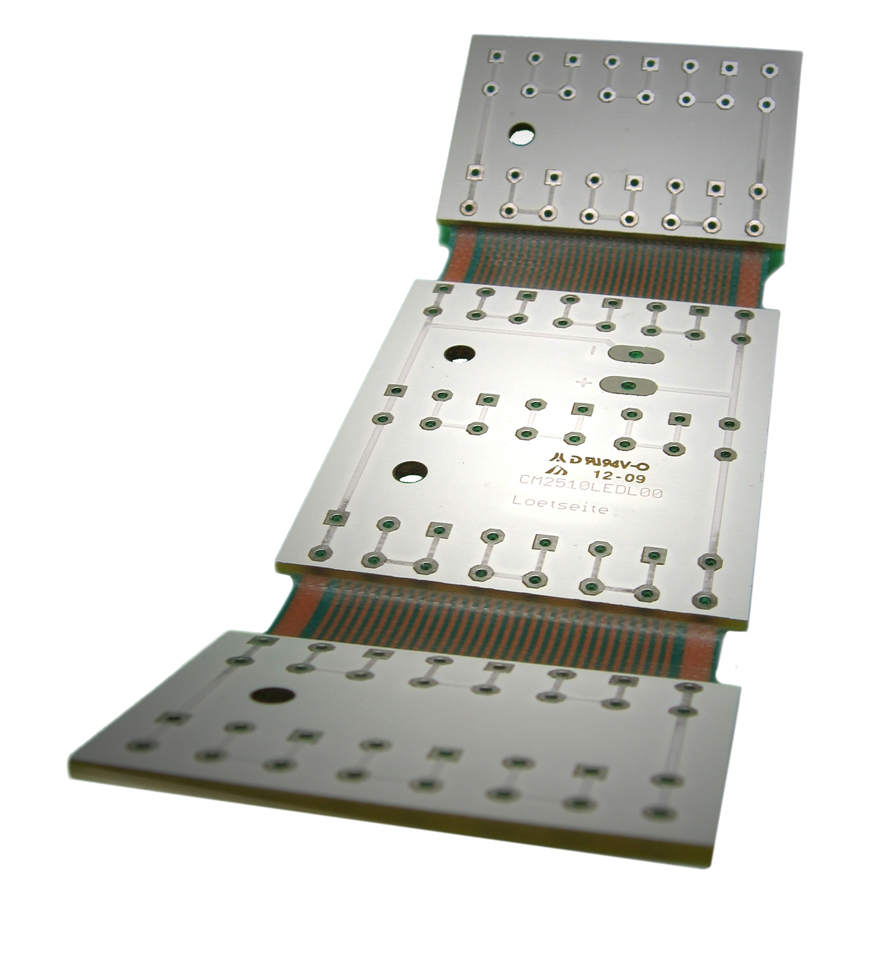
It is to be considering that a full up mechanical layer is a fundamental indication as it should provide us all the needed mechanical information for the construction of the correct pcb. In the case of any kind of slots present in the pcb, the mechanical layer is mandatory to the production.
Note: the mechanical layer should be 1 to 1 (so no scale it) and reflect the exact dimensions of the pcb; it is also viewed from top to bottom through the pcb, so do not mirror the mechanical layer ( for all layers ). Unnecessary information have not to be present in the mechanical layer.
Routing datas always depend on production machinery and capability (rout tools, tool compensations, routing order and direction) and none PCB fabricator use the same. Only a correct mechanical layer must be provided.
Note: a customer routing layer is unusable, because it has to be completely reworked during CAD/CAM operations; moreover it could generate confusion and/or misinterpretations which may result in wrong boards.
- The exact board outlines
- Exact positions and sizes for all inside milling, slots or cutouts
- Ideally the dimensions of all details (mm or inch)
Important note: when no dimensions are given, the outline of the pcb or other mechanical particular will be considered on the center of the contour lines, regardless of the thickness of those lines.
- the distance ( X and Y ) from one drill hole to the PCB outline (reference hole) particularly when the pcb has only NPTHs without copper pads;
- a drill table/map which is the positional/dimensional indication of all drills using symbols. It is important to use different symbols for each different drill size; any way this map is used only to cross-check the drill file(s) for correctness and it will be never use to generate any drill process because it could give to many possibilities to do mistake in production.
- helpful PTH/NPTH indications for holes and slots;
- panel’s data including all indications for break-routing and/or scoring (V-cut) if the pcbs must be delivered in panel format;
- Dimensional tolerances on board outline, PTH or NPTH and slot or cut-off if tighter than the standards values ( only for PcbOnDemand service);
- the build up details including all copper, soldermask, legend and any additional other layers like peelable mask or carbon ink.
Other values could be obtained by PcbOnDemand service only. Any way a requirement for a smaller radius on inner corners should be clearly indicated in the mechanical layer.
Note: placing a NPTH drill on the board outline in the center of the inner corner or any way inside the inner corner could reduce that radius to different lower value.
Generally it could be considered:
Tolerance on slot dimensions
Width= +/-0.15mm (+/- 6mil)
Length= +/-0.20mm (+/- 8mil)
Tolerance on contour dimensions
Routed boards= +/- 0.15mm (+/- 6mil)
Scored (V-cut) boards= +/- 0.20mm (+/- 8mil) (=+0.4/-0.00mm after board separation)
Tolerance on position of hole to contour or to slot/cutouts= +/- 0.20mm (+/- 8mil)