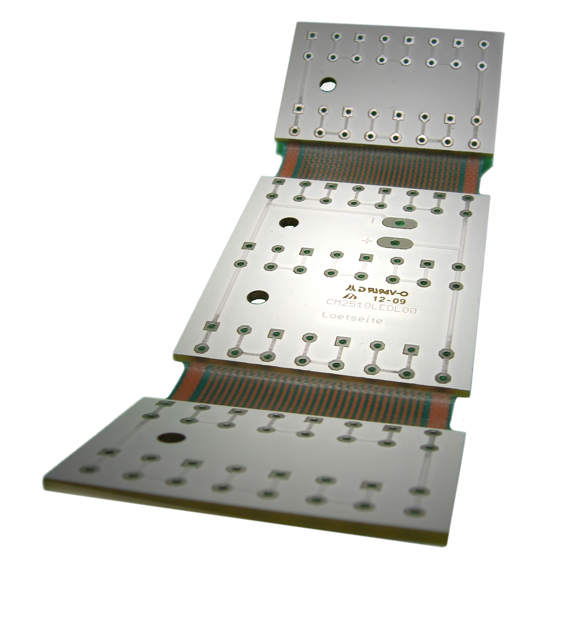
1. “Flashes” for pads are required when generating output; it is kindly suggested to use not “painted” pads (i.e. pads filled with small draws) nor for big copper area or copper planes: in these cases it is suggested to realized a
2. The board outline must be also present in the copper layers: to do this, it is
3. All copper pads must be removed from NPTH hole’s positions if those pads are not used or connected to any track or copper area. If any copper pads
Important features (for
4. Small areas of unconnected copper or narrow copper webs and slivers which can lead to problems in production, must be not used if not absolutely needed.
5. Thermal pads ( PTH ) should be properly defined considering the pattern classification of annular rings, track widths (thermal segment) and gaps.
6. Copper plane or copper fulfilled areas should be realized with full copper lay out rather than grid patterns. If grid patterns
- Minimum tracks width of grid = 0.125mm (5mil)
- Minimum track to track gap ( no copper area) = 0.125mm (5mil)
Important note: any copper grid that does not meet these minimum requirements could be converted into a full copper plane.
7. Due to the alignment tolerances between drawing and mechanical processes during production, a minimal clearance between
- routed boards:
- 0.20mm (8mil) on outer layers
- 0.40mm (16mil) on inner layers
- scoring boards (V-cut):
- 0.40mm (16mil) on outer and inner layers (if
- 0.30mm (12mil) on outer and inner layers (if
Note: if the
8. Only PcbOnDemand service allowed to do the copper plating of the board edge (or part of it): this must be clearly indicated in the mechanical layer.
9. Any text placed in a copper or other layers has to comply with the design rules (depending on different class).
Note: all text must be correctly readable, so considering that a
10. “Peelables” occur during production when thin/small/short/narrow pieces of photo resist material enclosed by pads, traces and/or planes peel away during processing, causing short or open circuits in the
11. For gold connectors (fingers) do not place any plated holes (PTH), SMD or other pads closer than 2.00mm (80mil) to the gold fingers.
12. The proper layer sequence for a multilayer board must be provided:
13. A Build Up specification must be included in the
Note: include a simple ASCII text file with the data indicating which file is to be used for which layer, preferably already in the correct build-up sequence (this is the least preferred solution: it is better if the build-up is indicated in the Gerber data as in the previous 3 suggestions).